I hard-wired my radar detector today, thought I would put together a DIY since I had to figure this out for myself because I couldn't find a DIY guide online! This guide is to install it clipped onto the passenger side sun visor, but you can reroute the wiring to set it up wherever you want.
Disclaimer: Don't break stuff. If you do, don't blame me as I accept zero liability. Ask questions if you're unsure and I'll be more than happy to answer them.
INGREDIENTS:
Pliers, electrical tape, a socket wrench with a 10mm socket and one or two 20amp mini ATM fuses. Heat gun optional. You MAY want to buy a spare 20amp fuse or two. In case you drop the 20amp fuse into the bowels of the glove box fuse box hell and never find it again. Mini fuses - ATM mini fuses.
A) ATM Mini Fuse Tap. You can find these at most auto parts stores. My local NAPA store had one in stock.
![Image]()
B) Ring wire connector. I'm not 100% sure which size (sorry) but it was at least 4mm inner diameter:
![Image]()
C) Spudger, or another plastic tool. I suppose you could use a dull butter knife but I don't recommend it as it will be used to wedge some trim apart for a few moments. I had a ton of these laying around because I work on computers a lot:
![Image]()
D) You'll also need the V1 hardwire kit that came with the radar detector. Specifically, the rounded module piece:
![Image]()
Mine has two thin wires coming out of the back (not pictured), one red (12v power) and one black (ground).
The kit also has a long telephone-wire-looking cable. You want that.
RECIPE:
What we're tapping for power is a 20amp fuse. Specifically, the windshield wiper fuse. This fuse is hot with power, meaning it only supplies power when the ignition is on. This way, your detector will shut off when you shut the car off. It won't drain your battery. It's also 12 volt.
Turn your car off.
1. Empty your glove box. Grab the sides and push them inward in order to lower the glove box completely, because we're going to tap a fuse in the fuse box located behind the glove box.
![Image]()
2. Pull the 20amp fuse out of this location and for god's sake DONT DROP IT!
![Image]()
2a. Take the 20amp fuse, and plug it into the fuse tap (A) so that you don't lose it for now. Take one of your other 20amp fuses and plug it into the other fuse slot on the fuse tap.
2b. Sorry I did not take photos of this step but it's not too hard. Message me if you have questions! Take the red 12v power wire from the radar detector kit module (D). Now, mine did not have anything at the end of it - it was simply severed. What I did was strip some insulation off the end of it, and connect it to the long purple wire coming out of the the fuse tap (A) that has a connector and heat-shrink tubing on it. Insert the wire, crimp it down with some pliers, and if you have a heat gun, go ahead and heat shrink it. If not, just wrap it up well with some electrical tape.
3. Take the black wire coming out of the kit module (D) and do the same as the other wire - strip the end of it, and push it into the ring wire connector (B). Crimp it down, heat it up, or wrap in electrical tape.
4. Back to this picture:
![Image]()
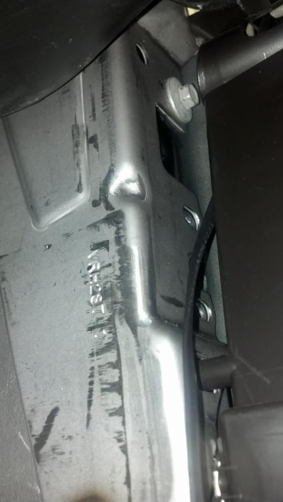
See that stud/nut to the right? That's your ground. Get your 10mm socket wrench and take the nut off. It takes quite a few turns. Don't drop the nut!
5. Plug the fuse tap into the fuse location that you pulled that fuse out of earlier. The one I circled on the left.
6. Put the ring wire connector (ground wire (B)) on the stud, and tighten the nut back down. You may notice that the fit isn't great, because the stud is in a recessed dimple, but the ring wire connector is flat so it wants to go on at an angle. You can just bend the ring wire connector near the base so that it sits down in that dimple. Tighten it up.
7. Test your detector! Do this before finishing up or else you'll kick yourself if it doesn't work. Plug the telephone cable (I mean, that's exactly what it looks like...) into the power port of the kit's module (D). Plug the other end into the radar detector. Turn the ignition and the detector on to try it out. Make sure your wipers still work too.
8. Working? Great! Move on. If it's not working, make sure you have two fuses plugged into the fuse tap and that they're both fully seated, and that the fuse tap itself is in the correct slot and also seated all the way in.
9. Unplug the telephone wire and grab your spudger or other thin plastic tool. You're going to insert it, carefully, somewhere along this dashed line:
![Image]()
While it's in there, wedge it open enough to feed the telephone wire (I keep calling it that) in through the crack and down into the fuse box area. Make sure you feed in enough of it.
10. Snake the wire forward towards the A-pillar. If you look carefully, there are panel gaps that you can fit the wire through easily. Do that, and keep feeding the wire up the A-pillar weather-stripping by peeling it back bit by bit:
![Image]()
11. Keep snaking it up the A-pillar. I followed this path:
![Image]()
...and up the front of the headliner. Here's a picture taken from the front of the car, looking backwards:
![Image]()
12. Keep feeding it over to the sun visor clip area. Mine ended up like this:
![Image]()
I had some extra wire left over so I just stuffed it up above the headliner at the top of the windshield.
Finally, go back to the glove box area. Plug the loose end of the telephone wire back into that kit module. The kit module should have adhesive velcro on it. I used that to fasten it to the passenger side of that fuse box area so that it wouldn't bounce around or rattle. You could also zip-tie it somewhere in there or just shake it until it stops crying. Umm..
Put your glove box back in. Just reverse the steps from earlier - push the sides in and put it back up in there. If by some chance you leaned on the glove box while it was in the down position, and it completely came off of the hinge (mine did!), it's not too hard to put back in correctly. Just push the sides in again and get the tabs on the sides of the glove box into the housing, then use your fingers to feel along the bottom of the glove box edge - the edge will have clips on it that snap onto the long black metal rod that it hinges on. You can snap one side at a time, it was easier that way for me. It takes a decent push to get it to clip back on there. You may want to look at the back of the glove box or the hinge it clips onto to get a better mental image of what you're trying to accomplish, since you'll be working blind and by finger feel only.
That's it. Enjoy. PM me if questions.
Disclaimer: Don't break stuff. If you do, don't blame me as I accept zero liability. Ask questions if you're unsure and I'll be more than happy to answer them.
INGREDIENTS:
Pliers, electrical tape, a socket wrench with a 10mm socket and one or two 20amp mini ATM fuses. Heat gun optional. You MAY want to buy a spare 20amp fuse or two. In case you drop the 20amp fuse into the bowels of the glove box fuse box hell and never find it again. Mini fuses - ATM mini fuses.
A) ATM Mini Fuse Tap. You can find these at most auto parts stores. My local NAPA store had one in stock.

B) Ring wire connector. I'm not 100% sure which size (sorry) but it was at least 4mm inner diameter:

C) Spudger, or another plastic tool. I suppose you could use a dull butter knife but I don't recommend it as it will be used to wedge some trim apart for a few moments. I had a ton of these laying around because I work on computers a lot:

D) You'll also need the V1 hardwire kit that came with the radar detector. Specifically, the rounded module piece:

Mine has two thin wires coming out of the back (not pictured), one red (12v power) and one black (ground).
The kit also has a long telephone-wire-looking cable. You want that.
RECIPE:
What we're tapping for power is a 20amp fuse. Specifically, the windshield wiper fuse. This fuse is hot with power, meaning it only supplies power when the ignition is on. This way, your detector will shut off when you shut the car off. It won't drain your battery. It's also 12 volt.
Turn your car off.
1. Empty your glove box. Grab the sides and push them inward in order to lower the glove box completely, because we're going to tap a fuse in the fuse box located behind the glove box.

2. Pull the 20amp fuse out of this location and for god's sake DONT DROP IT!

2a. Take the 20amp fuse, and plug it into the fuse tap (A) so that you don't lose it for now. Take one of your other 20amp fuses and plug it into the other fuse slot on the fuse tap.
2b. Sorry I did not take photos of this step but it's not too hard. Message me if you have questions! Take the red 12v power wire from the radar detector kit module (D). Now, mine did not have anything at the end of it - it was simply severed. What I did was strip some insulation off the end of it, and connect it to the long purple wire coming out of the the fuse tap (A) that has a connector and heat-shrink tubing on it. Insert the wire, crimp it down with some pliers, and if you have a heat gun, go ahead and heat shrink it. If not, just wrap it up well with some electrical tape.
3. Take the black wire coming out of the kit module (D) and do the same as the other wire - strip the end of it, and push it into the ring wire connector (B). Crimp it down, heat it up, or wrap in electrical tape.
4. Back to this picture:

See that stud/nut to the right? That's your ground. Get your 10mm socket wrench and take the nut off. It takes quite a few turns. Don't drop the nut!
5. Plug the fuse tap into the fuse location that you pulled that fuse out of earlier. The one I circled on the left.
6. Put the ring wire connector (ground wire (B)) on the stud, and tighten the nut back down. You may notice that the fit isn't great, because the stud is in a recessed dimple, but the ring wire connector is flat so it wants to go on at an angle. You can just bend the ring wire connector near the base so that it sits down in that dimple. Tighten it up.
7. Test your detector! Do this before finishing up or else you'll kick yourself if it doesn't work. Plug the telephone cable (I mean, that's exactly what it looks like...) into the power port of the kit's module (D). Plug the other end into the radar detector. Turn the ignition and the detector on to try it out. Make sure your wipers still work too.
8. Working? Great! Move on. If it's not working, make sure you have two fuses plugged into the fuse tap and that they're both fully seated, and that the fuse tap itself is in the correct slot and also seated all the way in.
9. Unplug the telephone wire and grab your spudger or other thin plastic tool. You're going to insert it, carefully, somewhere along this dashed line:

While it's in there, wedge it open enough to feed the telephone wire (I keep calling it that) in through the crack and down into the fuse box area. Make sure you feed in enough of it.
10. Snake the wire forward towards the A-pillar. If you look carefully, there are panel gaps that you can fit the wire through easily. Do that, and keep feeding the wire up the A-pillar weather-stripping by peeling it back bit by bit:

11. Keep snaking it up the A-pillar. I followed this path:

...and up the front of the headliner. Here's a picture taken from the front of the car, looking backwards:

12. Keep feeding it over to the sun visor clip area. Mine ended up like this:

I had some extra wire left over so I just stuffed it up above the headliner at the top of the windshield.
Finally, go back to the glove box area. Plug the loose end of the telephone wire back into that kit module. The kit module should have adhesive velcro on it. I used that to fasten it to the passenger side of that fuse box area so that it wouldn't bounce around or rattle. You could also zip-tie it somewhere in there or just shake it until it stops crying. Umm..
Put your glove box back in. Just reverse the steps from earlier - push the sides in and put it back up in there. If by some chance you leaned on the glove box while it was in the down position, and it completely came off of the hinge (mine did!), it's not too hard to put back in correctly. Just push the sides in again and get the tabs on the sides of the glove box into the housing, then use your fingers to feel along the bottom of the glove box edge - the edge will have clips on it that snap onto the long black metal rod that it hinges on. You can snap one side at a time, it was easier that way for me. It takes a decent push to get it to clip back on there. You may want to look at the back of the glove box or the hinge it clips onto to get a better mental image of what you're trying to accomplish, since you'll be working blind and by finger feel only.
That's it. Enjoy. PM me if questions.


